Habitation Wiring
Habitation Wiring Diagram
Daisy's habitation wiring is essentially four largely separate circuits.
The simplest is a transformer located on the bulkhead behind the battery and connected to the hook-up 240v. Charge is supplied to the battery via a diode which ensures there is no loss of charge across the transformer when the hook up supply is not connected. The transformer has its own built-in fuse.
The second circuit comprises a lead from the vehicle ignition (A14) which closes a relay (R1) to complete a circuit between the vehicle and leisure battery when the ignition is on. This lets the alternator charge the leisure battery when in motion. More modern vehicles have technology to reduce the alternator current if the vehicle battery is fully charged so that fuel is saved. This then needs a more sophisticated circuit. Daisy does not need this complexity. Diode D1 has been added because otherwise the starter motor circuit takes power from both batteries. This can be an issue of the vehicle battery has failed because it overloads the circuit designed for charging and makes diagnostics harder.
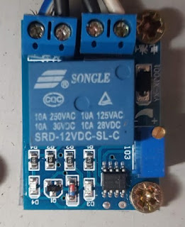
The third circuit comprises the master switch mounted in the door well, a relay and a low voltage cutout. The habitation battery feeds power through the master habitation fuse F1 to the switch. The return from the switch sends power to the low voltage protection. If the voltage is higher than the threshold (set by adjusting the small screw on the unit) then electricity passes to the relay. If not then no electricity is passed and the relay remains open. The screw is copper coloured and mid-right in the image.
So in normal operation, the master switch closes relay R2 and connects the habitation battery to the habitation circuit. Should the battery be somewhat discharged then the low voltage protection will ensure that the circuit remains open and there is no connection.
The fourth section is the habitation electrics proper. Power flows from the relay to the fuse box with 8 separate fuses:
In the diagram below, the green fuses are glass fuses and the salmon ones are blade fuses. All are in the battery compartment.
Fridge: The fridge runs in 3 modes - when moving, on gas and on mains.
A21 is a permanent live feed to the fridge. There is a relay on top of the fridge (not shown) which is open or closed by A19, the feed from the ignition circuit. If the ignition is on then the circuit is complete, meaning that the habitation, alternator and vehicle battery are jointly powering the fridge.

So in normal operation, the master switch closes relay R2 and connects the habitation battery to the habitation circuit. Should the battery be somewhat discharged then the low voltage protection will ensure that the circuit remains open and there is no connection.
The fourth section is the habitation electrics proper. Power flows from the relay to the fuse box with 8 separate fuses:
- Pumps and tank level sensor (but not toilet flush pump).
- Gas valve and gas heater ignition
- Water heater
- Lights: Over table, bulkhead, luton area and overhead.
- Toilet light and flush, kitchen extractor and light, cupboard light
- Centre and top left cupboard lights, fan on heater, centre console USB port, amplifier and voltmeter.
- Fridge and fridge ignition. Note that the fridge has 4 12v feeds.
- Door well USB and auxiliary socket.
In the diagram below, the green fuses are glass fuses and the salmon ones are blade fuses. All are in the battery compartment.
Fridge: The fridge runs in 3 modes - when moving, on gas and on mains.
A21 is a permanent live feed to the fridge. There is a relay on top of the fridge (not shown) which is open or closed by A19, the feed from the ignition circuit. If the ignition is on then the circuit is complete, meaning that the habitation, alternator and vehicle battery are jointly powering the fridge.

Comments
Post a Comment